Build a CNC Router for Under £600

[ Part 1 ]
There’s no doubt, a CNC router machine is a great asset for any sign business. They can be used to cut lettering in a range of materials such as plastics, aluminium composite,mdf, wood and HDU. They can also be used to carve dimensional signs much quicker and more accurately than you could hope to do by hand. I have often contemplated investing in such a machine for my business but have been put off by the high cost.
So when I heard about a book describing a DIY version that could be built for under £600 I decided to go ahead and shell out my “hard-earned readies” to buy it and find out more
I read the book from cover to cover a couple of times and I came to the conclusion that yes it probably was possible to build a CNC router machine at low cost. The instructions given appeared to be clear and concise, and there was nothing in the details of the build that I felt would be beyond the capabilities of any reasonably competent DIY’er.
I would also like to express my thanks to Graham Shand who came and spoke to me at great length about a machine he had built and offered me encouragement and support to go ahead and build one.
As a result, I decided the put my newly found knowledge to the test and decided to embark on a project to build my own CNC machine.
Not only would this provide me with an extremely useful tool for my business, but the build process would also educate me in the workings of such a device.
I also decided I would document the entire process from start to finish to use as a feature on the UKSB. However, this wasn’t going to be a step-by-step guide to building your own machine. No, the intention here was to document my journey from start to finish, warts and all. So that you the reader could follow my trials and tribulations to the eventual conclusion (which may or may not result in a fully working machine).
So what follows next is a series of articles describing my attempt to build my own low-cost CNC machine:-
Overview
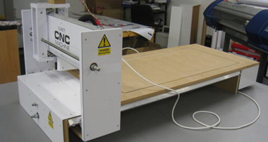
The machine I will be constructing has a table size of 4ft x 2ft. Not terribly big but still large enough to be able to produce useful work. The Carcass of this machine will be constructed using 18mm mdf which is readily available and easy to cut without specialist tools. However, I do have my own table saw (helpful but not essential) as well as a good selection of hand tools which will be needed to complete this project.
I have decided to construct the machine in stages. The first step will be to produce the machine’s frame (Carcass) and moving parts. Once I have established that the parts work as intended, I will then go onto stage two which will be to add the drive motors and control devices along with associated software and a suitable PC. These are perhaps the most expensive aspects of the project and I did not wish to jump in straight away and purchase these components before I was satisfied that I was indeed capable of seeing the project through to completion and not ending up with a “white elephant” on my hands.
Step 1
The machine’s table will consist of two sheets of 18mm mdf bolted together to produce a stable platform.
If you look closely at the following picture, you can see that the edges of the mdf have been chamfered at 45 degrees (this was easily done using my table saw – but can also be done using a handheld router and suitable chamfer bit as described in the book). This chamfered edge is necessary to provide seating for the gantry guide rails described next. Also shown in this picture are the two 90-degree angle aluminium rails that will be attached to the sides of the machine to allow the x-axis gantry to run smoothly fore and aft along the length of the table.

In this next picture, you can see that the top and bottom halves of the bed making up the table have now been bolted together and a close-up of the resulting 90-degree seating for the guide rails to fit onto. Also shown in this picture are the two bearings that will be used to provide a smooth action for the drive screw that is required to carry out its task of moving the x-axis gantry.

This next picture shows the series of components that will all be fastened together to produce the x-axis table.
From left to right we have the two table legs that will be attached to the front and back of the machine.
Next, we have the two-angle aluminium guide rails already described.
Next is a length of threaded rod that will provide the drive mechanism.
Finally, we have the two halves of the table already bolted together ready to be assembled with the rest of the components making up the x-axis bed. Sitting on top are the bearings for the threaded rod drive screw mechanism.
All these parts can be readily sourced using the internet and/or your local hardware store (amongst other sources, I found screwfix.com to be a very useful and cheap supplier for the many different types of fixings and screws required to proceed with the build).

And in the final picture, you can see how all the parts just described fit together to form the main x-axis bed of the machine.

So far so good. Everything has gone fine up until this point. Nothing was particularly difficult to do and the resultant bed seems strong and stable enough.
The next step in the process will be to start building the x-axis gantry that will run along the length of the machine.
So far I have only spent £115 on parts and materials. some of which have not yet been featured but will be used later in the machine’s construction. So if it all goes badly wrong, or to use its more common technical term – Tits-up! I won’t have spent a fortune finding out.
[ Part 2 ]
At the end of the previous exciting instalment of “build your own CNC machine,” I was left with the main CNC table fitted with side rails. The next step is to construct the X-axis gantry that runs up and down the length of the table
Before constructing the gantry, it is first necessary to produce the roller bearing system that will support it and provide a low friction means of allowing the gantry to run backwards and forwards
The bearing system is made from roller skate bearings as seen in this next picture. Alongside are the nuts and machine screws used to fasten the bearings to a 7″ length of angle aluminium. Amazingly, these bearings cost me under a tenner to buy the 24 required for all three axes of the machine. But would such a cheap and cheerful arrangement be up to the job?

The drilled angle aluminium must first be tapped to allow the machine screws holding the bearings to be fitted. This next picture shows the tool used to cut the thread into the angle aluminium

The machine screws are inserted into the bearings as shown and fastened tight using nuts.

Next, the bearing assemblies are screwed tightly onto the angle aluminium to produce a BRA (bearing rail assembly). The next picture shows a BRA sitting on top of an offcut of angle aluminium demonstrating how the mechanism will slide along (two of these assemblies will be used for each axis).

This next picture shows the components used to make up the X-axis gantry.
Looking from left to right we have the drive nut (an ordinary nut) inset into a piece of MDF. (This nut is what will provide the drive motion when the threaded rod is turned pulling and pushing the gantry). Alongside this are the top and bottom pieces of the gantry, and finally, on the far right are the two gantry sides with BRAs already fitted.

In this picture, you can see how the components fit together. The gantry will literally “wrap around” the main table

This picture shows the lower section of the gantry temporarily fitted into place to demonstrate the principle of construction

Now we can see the gantry fitted around the main table. This view is of the underside demonstrating how everything fits together including the threaded rod (screw mechanism) that will power the gantry

And in this final picture, we can see a front view of the machine.

I have now reached a critical test phase. The next step is to test the motion of the gantry by turning the screw. When the machine is finished, the screws (there will be three in total, one for each axis) will all be powered by their own dedicated motors. Meanwhile, I am about to test that everything works as it should by using a handheld variable speed drill.
Next, I tightened the chuck around the threaded rod… and gingerly squeezed the trigger…
Total build costs to date remain at £114.98 including VAT, with postage and delivery charges of £28.59
[ Part 3 ]
At the end of my last report, I finished up by testing the X-axis movement using a handheld power drill to turn the drive screw and successfully moving the gantry up and down the table. I was delighted with the result and now felt confident that I could finish building the machine.

With the table and the X-axis gantry now completed and tested, it was time to move on and build the remaining Y and Z axis of the machine. First the Y-axis:-
In this next picture, you can see the Y-axis components consisting of the top and bottom complete with BRA’s already fitted along with the supporting sides of the axis.

Here you can see the assembly being put together

And another picture of the Y-axis under assembly

The final component is the Z-axis – this is the part that the router tool will be bolted to.

Here is the Z-axis fully assembled sitting alongside the Y-axis. Also shown in this picture are the angle aluminium rails that will be fitted to the Y-axis to allow the Z-axis to move up and down.

And in this picture, we can see how the Z-axis wraps around the Y-axis. This combined assembly will now be fitted onto the X-axis gantry to provide a full X, Y Z series of movements

Finally the completed assembly

And another view

I now have a completed carcass – the next step is to add the drive motors and electronics that will be used to control the movements of the machine via a PC.
My thoughts so far are as follows:-
The build process has been very quick and easy to follow provided I stuck to the original plans as laid out in the book. On reflection, I don’t think I could have achieved the degree of precision required had I used simple hand tools to cut the MDF. In retrospect, a table saw is an almost essential piece of workshop equipment required to build one of these machines. I was fortunate that I had most of the tools required as part of my sign-making armoury of tools.
The only area I found tricky was the use of imperial measurements used in the plans. I had to convert most of the specifications to their metric equivalent in order to source suitable hardware such as the bearings and fixings used.
But before going on to the next step I have one final piece of work to undertake. This is to clothe the machine using a combination of composite aluminium panels and vinyl wrapping (In the video above you can already see the first part of this process where I have fitted an aluminium composite panel to the X-axis gantry). This step involves completely disassembling the machine but will be well worth the effort. I had decided at the outset that I wanted a professional finished look to the machine. Clothing the machine in this way would also impart additional strength where composite material was being used. And by wrapping all of the components I would be protecting the machine from possible damage from moisture which has a tendency to cause MDF to swell if untreated (the untreated MDF was already looking pretty grubby in places where it had been stained by grease and dirt during the construction process).
Part 4
At the end of my last report, I had completed the carcass of my machine:-

However, the bare mdf would need protecting and additional strengthening. I decided to do this by wrapping many of the components and by adding cover plates made from 3mm composite aluminium.
In this next picture, you can see I have begun to wrap one of the Y-axis gantry sides using white vinyl

And here you can see some of the components already wrapped. Note also that I have countersunk many of the fixing screws to allow me to fit cover plates flush with the surface of the panels

And here are the composite aluminium cover plates that I have made up. These will also be screwed onto the machine to provide protection and additional strength. (Note some of the panels have been grooved and folded at 90 degrees)

Fitting of the cover plates is in progress


I also decided to add a dust extraction system to the shoe that will be used to hold the router in place on the machine. Here you can see the underside of the shoe with a channel carved out to connect the vacuum suction to the hole where the router bit will be situated

The channel is covered up with a plastic cover to direct the suction to the point where it will be needed most.

Top view of the shoe

And in this next picture, we have a picture showing a close-up of the router bolted into place on the shoe with the dust extraction system (A Henry Hoover) connected up

Finally, pictures of the fully clothed machine


Total expenditure to date has been £115 + £35 (composite material, vinyl and hardware) + £40 (Handheld router – I already owned one but this would have cost me £40 to buy new) = Total £180 Inclusive of VAT
(In addition, I have spent £28.59 in delivery/postage charges for some of the hardware)
(The Henry Hoover is my workshop machine which I already owned and use for tidying the workshop, so I have decided I will not include the cost of this “dust extraction system” as part of my £600 budget)
It’s getting really exciting now – but I have reached the point where I will have to dig even deeper into my pockets and spend a bit more cash to buy the motion electronics…. so I think I will just go and have a little lie down for now :worry:
Don’t forget to look out for the next exciting instalment of “Build your own CNC machine” by which time I should have recovered my composure at the thought of having to shell out more readies!
Part 5
At the end of my last report, I had a brand new shiny carcass awaiting the motion electronics to bring the machine to life

After what seemed like an eternity, finally, the parts arrived from America. Unfortunately, these were subject to an import duty of £56, which I had to pay before the delivery company could release the parts to me.
The next picture shows the parts set out on my workbench. Consisting of 3 motors. 3 motion controllers. A power supply. A break-out board (this allows you to connect the PC to the CNC machine via the computer’s parallel port). An emergency stop button. 6 limit switches and 3 motors to drive screw couplings. The total cost for all these parts was £328 with an eye-watering £75 delivery charge.

However, what I discovered next, made me think my plan had backfired! (puppy-eyes)
The colours of the wires coming out of the motors were different from the colours described in the plans I had been following. Not only that, but the breakout board was also different from the one shown in the book’s plans. And finally, the three motor drivers (although they looked the same as the book’s drivers) had different numbers and lettering at each wiring point.
At first, I was baffled, but after careful research, on the internet, I eventually figured out how to go about wiring everything up

The picture above shows the wiring partially completed. I decided to mount all of the components onto an offcut of mdf which was recommended in the book. Slowly and methodically I connected each wire and fitted the motors to the machines carcass which can be seen in the next picture

And in this next picture, we have the completed machine. Note also I have installed an emergency stop button and fitted a sacrificial cutting board onto the machine.
(This was another piece of 18mm mdf which was screwed on top of the machine cutting bed).
I had already installed the software to control the machine. This is called Mach 3 and is available as a free trial version to download from the Mach Support website.
So with great trepidation, I carefully plugged everything in ready to begin testing.
Here is another picture of the completed machine all plugged in and ready to go

After one or two false starts (at first, nothing happened – despite plugging it all in everything remained dead…until I realised that I hadn’t plugged the parallel port cable into my machine) :doh: I was ready to run my first test cut.
This video shows the machine’s very first test cut. (Honest Guv – this is a piece of history, this is a genuine unstaged recording of the very first time the machine ran under its own control).
I was overjoyed at the machine’s maiden voyage. I felt like Doctor Frankenstein when his monster first came to life. To say I was grinning from ear to ear is an understatement.
Since then I have been learning to use the machine and have cut a number of test pieces which you can see next. These pieces are made from a range of materials including PVC foamboard, acrylic and composite aluminium

Conclusion
This project has exceeded my expectations. I really was doubtful that I could build something that was capable of doing real work but this one does.
To all intents and purposes, it is now finished and up and running though will benefit from some further development.
The total parts cost was £603 including the cost of the router itself (I already had mine – but a new one would have cost me £40 so I have included this within my budget). I also had to pay £56 in import duty for the parts from America as well as £105 in postage costs. A Henry Hoover (dust extraction system) would have added a further £100 to the bill (again I already had one).
All software was free (I downloaded the trial version of Mach 3 which is free but limited to a certain amount of G code) I also used Lazycam (again free) and my own sign software to produce DXF files.
Next, I will be looking at buying some more user-friendly software and will buy the registered version of Mach 3 (This costs £110 and is well worth the price as it allows much bigger files to be run). The Trial version limits you to just cutting basic shapes. Anything complex will only cut so far before it runs out of code leaving a half-finished piece.
Was it worth the time effort and cost? Absolutely. I now have a machine that will be a great asset to my sign business. Not only that but I have learned a great deal in the process. And I have discovered a new hobby that I find exciting and have become quite passionate about. I have many ideas for projects I want to make on the machine along with a list of modifications I want to do to the machine to improve its performance and appearance, as well as putting systems in place to make it more user-friendly to operate.
More to follow soon where I will tell you all about the plans I have to improve the machine’s performance and looks even further
Part 6
Having completed the machine I decided to put it to some use making sample signs. All of the following were made using PVC foamboards of varying thicknesses. These were glued together in layers and coloured using vinyl


I also decided it was time to properly house the motion electronics.
Previously the machine looked like this.

As you can see there was no proper finishing of the motion electronics, these just lay alongside the machine and looked untidy as well as leaving a lot of exposed wiring.
I had also noted that I could increase the cutting area of my machine if I detached my sacrificial board and moved it forward to allow the router (which projected ahead of the table when fully forward on the
x-axis) to fully utilise the travel that was available. This would create an overhang to which I could then attach my motion electronics onto.

The next picture shows how my motion electronics board has been attached to the overhang created when the sacrificial board was moved forward. I also decided to box in the electronics using a piece of aluminium composite wrapped around the front edge

I now have a cutting area of 480mm x 985mm as opposed to 480mm x 840mm an increase of 14.5cm.
Note also – I used the machine to cut a rectangular groove into the bed to show the limits of the machine cutting area which is a useful aid when setting up pieces for cutting
A fourth and final improvement was to add a truss rod to the underside of the table. This is the same principle as used in guitars to prevent the neck from bowing caused by the tension of the strings
This next picture shows the underside of the machine with the truss rod in place

This is adjusted by tightening the bolt at either end which puts tension on the underside of the table and eliminates the sag

Finally, some more pictures showing the upgraded machine


Part 7
Previously, I mentioned that I had plans for some upgrades to improve the performance of my machine.
The first of these was to rebuild the Y axis with an “S” shaped gantry.
Before
After

The logic behind this was to move the centre of gravity back over the bearing rather than have a nose-heavy gantry caused by the weight of the router projecting so far forward. I also think it looks much better. There is an old engineering saying that says “If it looks right – it probably is right”
The second improvement was to add a device that would control the router speed – this is called a Super PID available from http://www.superpid.com
This would allow me to run the router at much lower speeds whilst retaining the cutting power of a high-speed router. The advantages of this are as follows:-
* Less noise
* The lower temperature of the cutting tool results in less melting and burning of the material being cut
* Longer bearing life
* The ability to control the router from the PC
* A rev counter display to show the speed of the router
These next pictures show the superPID electronics housed in the section of the machine where the rest of the motion electronics have been installed


A speed sensor is fitted to the router shaft to send a signal back to the superPID to allow it to control the spindle speed

The front cover was re-fitted, and a cut out made to display the instrument panel along with the installation of a manual speed control and an on/off switch

A further refinement was to configure Mach 3 (the software that controls the machine) to switch the router on and off and to control its speed of rotation.
Thus there are now three ways in which to control the router
1: Via the computer and Mach 3 using the superPID (By far the best way)
2: Locally on the Machines front panel using the superPID
3: Finally – bypassing the superPID using the router’s own manual controls (only used now as a last result should the superPID fail)
And finally, to prove the whole project was worthwhile -here are some pictures of the first commercial sign produced using my machine

This was made from butler Dibond cut-out lettering fitted to a gloss PVC panel and housed in a satin anodised silver sign frame.

At last, the machine was earning me some money (Instead of costing me money)!
Since then I have put the machine to good use and produced a number of signs, which, with the profit made, has more than paid for the construction of the machine:-


Acknowledgements:-
These machines build were closely based on the design described in this book:-
Build Your Own CNC Machine (Technology in Action) Paperback – 1 Dec 2009
by Patrick Hood-Daniel (Author), James Floyd Kelly (Contributor)
With further information from this website:- http://www.buildyourcnc.com
Without the information contained within this book and website, there is no way I could have hoped to build this. I did, however, stamp my own mark on the machine with a number of enhancements as already described in this series of blogs.
There is an old saying:- “The end result is greater than the sum of the parts” – I believe this to be true of this machine’s design.
I hope this tutorial has been easy to follow and is of help to you.
Phill Fenton
The Right Signs