Working with Colour Blends

Bob Gilliland has very kindly offered to help me with this by including an explanation of how the e6 version of Signlab would perform
I will be using Signlab Colormaster. The “Colormaster” module has the required tools that were used in this demo to create the colour gradient on the lettering. The printing and cutting have been done using a Roland printer.
The Blue “AKRO” lettering will be treated to a colour gradient, outlined and shadowed, printed onto white vinyl then contour cut to produce individual letters that were applied to the vehicle in the same way as conventional vinyl lettering.
Step 1 – First choose the fonts to be used and create the layout. (In this example I have decided to cut the “Multihire” part using red vinyl lettering in the normal way so nothing further will be done to this).

Step 2– The Blue “AKRO” group is selected in the normal way.
Click on the “pen” tool (left-hand side toolbar at the very bottom). This activates a fly-out menu. Click on the icon that looks like a red bucket of paint, this then opens up the “Attribute” menu shown below:-

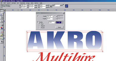
Step 3– The “Akro” lettering is to be given a linear fill (Second icon from the left). Click on this icon to open up the “Linear Fill” menu shown below:-

Step 4 – Check the box showing the grade type (in this case gradual change – as opposed to distinct stripes)
Next, select the two colours (from–to) in this case a white fade (white left-hand box) into blue (Blue right-hand box) – (Clicking on the coloured boxes will bring on a sub-menu allowing you to choose the colours to be used).
Next, select the “Repeat” type – For this example a single gradient from white to blue.
Finally click on “apply” to produce the effect shown below:-

(Note that in this picture – the image looks “stepped” which is due to the resolution of the images used in this demo – In reality – the colour change is much more gradual than this).
Step 5 – Next I introduced a dark blue outline and block shadow to the lettering. This is done using the transform menu (6 from the left on the top toolbar- sub menu drop shadows). The thickness of the outline required is entered into the box, and the size of the shadow itself is controlled by pulling on the red box around the lettering. Once everything is set up as shown, click on “apply”:-

This produces the result shown below:-

Step 6 – With the “AKRO” group selected – go to the “Cut” menu (Top toolbar – 5th from left) which will bring out the fly-out menu shown below:-

Step 7 – Check the box that shows cutting inside and outside the circle. Also, select the corner type (In this instance “round” is selected – in reality “Point” would have been be a better choice here). Choose a zero offset and finally click on “OK” to produce a dotted line along the inside and outside edges of the “AKRO” lettering. This produces the instructions for the cutter to contour cut the “AKRO” lettering later
The artwork is now ready to be sent to the Colorcam.
Step 8 – Cut out the red vinyl lettering in the normal way.
Step 9 – Print and cut the “AKRO” lettering by selecting the group. Now use the normal “Windows print manager” to send the print to the Colorcam. (This is very similar to sending a print to a conventional paper printer). The “cut” instruction performed earlier will ensure that after printing onto white vinyl, the printer should automatically go on to die-cut the “Akro” lettering.
Step 10 – Finally – The printed and cut lettering is weeded and taped in the normal way. This is then applied to the vehicle bodywork as shown. The conventional red vinyl lettering is then applied underneath:-

Having explained it my way – here is Bob’s version using e6:-
The following text is one approach to doing the same job inside SignLab e6.1 with the thermal module. Pictured directly below is a screen capture to illustrate some of the differences with e6 as well as the thermal module.
The smart bar, by default, is located directly below the drop-down menus. This area is “smart” in the fact that it changes to reflect options relative to the tool or procedure that currently active.
You can customize the position and content of the toolbars. The toolbar along the left is a “default” toolbar while most of the other toolbars are “customized” or added by me.
The “job” palette on the right hand side has two views, color or foil. The current view is “color” and displays all the colors that are in use on this job along with primers and halftones. This job palette is updated “real time” and makes it very handy for drag and drop procedures, replacing elements, or seeing what foils are in use amongst other items that aren’t reviewed here.
The “halftone” palette contains settings for Knock Out/Overlap/Overprint settings (not all settings applicable to Roland ColorCAMM), primers, and halftones.
The “layers” palettes contains all layers used which can be a combination of both print, cut, and print and cut. In Phill’s example, we will put the Red cut only copy on a separate layer in order to better manage the job
The last one to point out is the “Shop” palette. This, from a thermal perspective, is generally geared towards spot swatches and predefined process color swatches.
Our approach to this job will use a spot color gradient fill using the “Spot Gradient Fill” tool. The smart bar for this tool is pictured below. The left hand side of this bar allows you to pick from a linear, radial, or square “fill” gradient. Working towards the left; the unlabeled box enables two spot color gradients for a single object. This would allow a Red into Orange spot gradient with a single operation. No check in this box (as reflected below) allows for a single spot color. Clicking on the down area by the color swatch will give access to all eligible spot colors from the current shop palette. Hovering over a swatch will produce a pop up bubble that indicated the manufacture, color, and code if entered. The slider allows control over how the gradient will produce. In this example, we have a simple 100% color to 0% liner fade. Double clicking on the slider bar will produce a control node that can allow more control for the gradient. SignLab has on screen hot previews that allow you design from an optical standpoint, or, you can do the same from a “mathematical” standpoint by entering values for “Angle, Y, X”. The last item, a floppy looking icon, allows this gradient to be saved as a predefined swatch for use later.

Now that the spot gradient has been applied, we’ll move onto the drop shadow with outline. Pictured below is the smart bar area for the “shadow” tool. The smart bar area goes a long way in keeping the working area free from clutter allowing for better, more productive design time. On screen control of the shadow is available like Phill demonstrated with version 5. The “square” control nib controls how much of an outline is applied with the “circle” control nib (upper left hand area) controls the depth and location of the shadow. Some additional options available are how the corners are handles, if a relief shadow is to be applied, and at what thickness. Shadow types are Block, Perspective, Drop, and Cast.

It hasn’t been reviewed in great depth, but I have elected to use the layer feature within e6.1 that allows for greater object control. I have two layers enabled for this job, a print and cutting layer, called layer 1, that contains all “AKRO” related items. Layer 2, a cutting only layer, has the “MULTIHIRE” copy. On a cut and print layer, a cutting path needs to be created for any area to be cut. Pictured below is the smart bar relative to assigning a contour cut. I have elected to “undercut”, or reduce the cutting path by .020mm, to insure that none of the White, unprinted vinyl is exposed when cutting. This is commonly referred to as a bleed.

Pictured below is a close up reflecting a “Green” cutting path.

And additional feature with the e6.1 thermal module is the ability to move into a “Print and Cut” manager. This allows for greater flexibility (which will be reviewed later) to both the ColorCamm and Edge devices in a production fashion then is currently supported.
This wasn’t an all encompassing step by step, but approached more from pointing out some of the differences between 5 to e6.1 with the thermal module. Far more control and flexibility is included within the thermal module that makes it a “must upgrade” in my opinion for current SignLab users. And a package for serious consideration for non SignLab users. The ability to design, and then have the ColorCamm easily use such without much end user manipulation, should allow for some further design exploitations that were undesirable because of the additional work, or overall lack of tools necessary to do such before.
And I would like to close out by saying a small, personal thank you to Phill for allowing this additional information to be include within his step by step.