Building Better Aluminium Sign Frames
Over the years, during the construction of a sign, there have been many instances that I, or my staff, have forgotten to do something or have left a tool or piece of the sign frame back at the workshop. This can quickly cost you time and money! As a result, I believe that if the majority of a sign can be constructed “in-house”. Then it should be done “in-house”

Aluminium trim or Panatrim fascia
These consist of four sides/lengths of trim and a sign panel, so what is so difficult?
The signs we see on the high street are often not running true, so they are skewed or tapering down at one side. Some sign panels do not fit snugly and blow out, while others lose a section of the frame because it is not fastened correctly. Anyway, I will try to explain in this demo how I overcome these problems when it comes to common sign frames.
Tools Required:


The following sign size is approximately 3 metres x 762mm
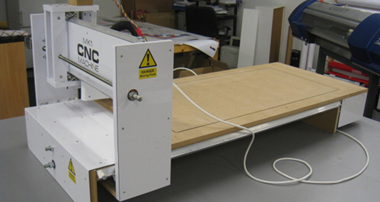
Pictures 1 & 2
Picture one shows you the different parts of the sign frame that I am about to assemble.
- Top & Bottom lengths
- Both the left and right sides
- Three 2mm aluminium backing straps
- 25mm x 25mm aluminium Corner angles
The purpose of each section/piece will be explained as we proceed through this demo.
Lengths 1, 2, 3 & 4 have been cut and mitred from lengths of Panatrim aluminium frame.
Panatrim is just the brand name of the trim I am using in this instance. It comes under a variety of other names for similar types of aluminium extrusion.


Picture 3
Picture 3 shows a close-up of one end of a sidepiece of Panatrim. “Length 3”
Where you see the trim has been chopped by a mitre saw, you also see a little holding slot where the angle piece easily slides into as shown. Some trims do not have this slot but work just the same

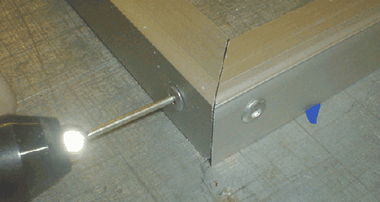
Picture 4
Picture 4 shows once the angle is in place. Take a drill and drill one hole through the angle piece and the Panatrim as shown. Be sure to sit on top of a waste board to drill into so as not to blunt the drill bit!

Picture 5
Picture 5, after having just inserted your angle to the end of your sidepiece of Panatrim & drilled a 5mm hole through both trim and angle. You want to make both secure by fixing a single rivet through them both. Riveting should be done from the outside in as shown.

Picture 6
After having repeated steps 4 and 5 on each end of the side pieces of trim (lengths 3 & 4)
You should be left with something that looks like picture 6.

Pictures 7 & 8
Picture 7 shows the joining of the end pieces. This is easily done by sliding the exposed parts of the angle Into the top and bottom lengths of trim ( lengths 1& 2 )


Picture 9
Once you have slid the ends pieces into the lengths of trim (lengths 1 & 2) you are once again ready to drill into the sides of the angle. Again from the outside in. but this time be sure not to let the join open or move. It is very difficult to re-drill it, as the first hole will be so close to the second. It will also leave an ugly finish to the side of the trim due to the extra hole.
Once drilled apply the rivets. Rivets at this point should only be put in one side of the sign frame.
So as the other side can be left off to slide in the sign panel.

Picture 10
Applying the backing strips. This is particularly easy to do but very important to get right.
I have cut 3 lengths of aluminium. 30 inches by about 4 inches. It is better to have the strips broader than narrow. The breadth of the strip keeps the frame square and stops the trim from going askew…
I have come in approx 8 inches from the edge. The reason for this is to be close to the edge but not too close. This prevents the sign from tapering towards the ends. Thus preventing a tight fit for the sign panel to be forced into.
Having checked that your backing strips are exactly the depth the sign should be. Make sure they are very flush / square with the top and bottom of the trim. If so. Go ahead and drill and rivet. Making sure before each hole is drilled that the strip is still flush.
Put a minimum of two rivets on the top and bottom of the backing strips. Again this will prevent the sign from moving off-square.

Picture 11
This picture shows what the frame should look like when complete. Remember one end of the trim is only slotted into place and not riveted. This is to allow the sign panel to slide in.
You can see the 3 backing strips. Two 8 inches in from each side and one in the centre. The longer the fascias sign the more backing strips to use. I once did a 30-foot-long sign like this. Done exactly the same way but in 2 pieces. Again I had a backing strip right on the join for extra strength.

Picture 12
The last thing to do is drill holes.
I have evenly spaced holes on the trip and backing plates. Again drilling may sound like something that only takes a min or two on-site. But doing it in the workshop cuts back on time climbing up and down ladders for drills etc.
I also know some times drill isn’t any use as some holes may not catch. The idea is that some holes may also catch. And enough to let you get the sign in place at least.
The biggest and most important hole I think for a sign like this is to drill the top centre,
If you get it bang in the middle it is just a case of putting one screw in the top middle hole to hold the sign. Then put your spirit level on the top of the trim, “rock” the sign level and put in the second screw to hold strong.

Picture 13
This picture shows how the sign panel will be slid into place.
Picture 14
This picture shows that the sign I am fitting has raised Perspex letters on it. Again I have applied my template.
Drill and part screwed the female locators into place to prevent me from having to do it on-site.
Once slid into the frame. I take a cordless screw gun and sink each locator home… if I had done this before sliding into the frame.
The screws may have interfered with the backing strips because the screws were one inch long.

Picture 15
This picture shows where in most cases the rivet stub interferes with the sign panel. I normally use a hacksaw or jigsaw and cut this small piece from the panel to allow a snug fit with the trim…

Picture 16
This picture shows a completed sign frame with no sign of flexing or movement. The corner brackets, mitres and backing strips hold the whole sign frame together making it very stable to handle.

Picture 17
The sign frame is ready to fit.
Holding the frame easily with one hand. This shows that the frame can be lifted up a ladder in one piece. Making fitting very fast & easy. Remember all those predrilled holes? Now only a cordless screw gun and spirit level are needed unless drilling into masonry.
Once I had my ladders etc in place the sign, including raised letters applied took me only 15 mins onsite.
The fact I had constructed the whole sign in-house I knew there would be no problems with trim fitting sign or any other silly hiccup that occasionally crops up with simple sign work like this.

“how is it possible to front load a fascia sign if it can’t be loaded from top, bottom or sides..?. “
hope this helps!
below you can see a mock-up of a fascia panel with a panatrim-type trim to it.
signs like this should have a hanging bracket attached to it like it is shown in the picture. these can be glued on but in most cases, it’s wise to put a few small screws in place. depending on the constant weight it will hold…
please excuse the sample I have used. the panel is 3mm Composite so you can
see a bit more space at the back of the panel rather than what it would be with a 5mm perspex.
as you can see if the panel was slid-in, in the normal fashion it will not fit, due to the hanging peace.

what to do here is lift the panel from the bottom out… keeping the top inside the trim as shown in the next picture.

once you have got it in and under the lip.. push it up so it touches the top of the trim in the inside. as shown in the next picture.

Next, you would push the bottom part of the fascia board back into the lower trim. this should slip in easily & left to hang in place.
the picture below shows the sign bracket in place but also shows the panel hanging out at the bottom.

next are two blown-up pieces of the picture above.
picture (a) shows the bracket hanging. if you look closely you will also see two red lines with arrows. this shows the play that you above the panel this play is what you have have to get the panel into place. for easy talking ill say that space is .75 inch
now look at the bottom blow up… picture (b)
it shows that I have not a full-length panel but a panel with only enough to catch the trim at the bottom. the amount of trim you have to catch at the bottom relies on the amount of play you have at the top. the more play at the top the better…

again i said it was .75 inch play. so the overlap at the bottom will be something like .72 inches.
if the size is correct and just enough. the panel should slot in at an angle at the top. keeping it tight up & on a hinge effect move the bottom into the back of the frame and let it drop into the groove as shown below.

your opinion on what the finish is like is probably like my own. it looks pretty fragile and would move a bit with the wind.. but bear in mind the panel shown is 3mm thinner than what should really be used.
[size=134]”This seems a good way to put up a fascia with trim. but does it only apply to small signs like the one shown in the demo?”[/size]
the answer to this is certainly not!..
below you will see a fascia we recently put up. again it has been completely constructed in-house (workshop). once constructed the sign was slotted into the frame.
any joining pieces are fixed and lots of equally spaced screw holes are drilled in the frame.
all that was required to do now was transport and fit.
see below. one man easily lifts/works with a 25-foot by 47-inch fascia frame

once on site and trestles are put in place the frame was fixed into place in about 10 minutes.
the sign was slid in from one side and the end piece riveted on. 30 mins labour on site!
not bad…
the beauty of making a sign like this is that sometimes getting a good fixing is hard. If you don’t get the sign fixed where you want it. it can cause bother in the form of the frame sagging at bits. if this happens and you can manage to get away with it visually. you will normally not get away with it as far as sliding the sign-in goes. As it hits a sag in the frame the sign becomes tight and won’t slide any further. having the spars running down at the exact same height from the top helps to no end. even if the entire bottom piece of trim or vice versa was not screwed the top/bottom piece and all the screws in the spars would still easily hold the weight & the frame would not sag also….

in the picture above the frame actually has a join. the trim is 20 feet long but the sign is 25 feet.
from the right, not including the end piece of trim count back 2 spars. this is where the join is.
i will add to the replies with a few pictures on how to make a good join in the trim…